Do USB Cables Make a Difference in Audio? When Are They High Quality?
From: Vitor Valeri
A headphone hobbyist for over 15 years, he founded the Hi-Fi Hub website and is an administrator of the "Fones High-End" and "Fones Low-End" groups on Facebook.
Published in: 05/02/26 at 10:09
 Illustrative image of a USB cable being used in an audio system (Source: Vitor Valeri/Hi-Fi Hub)
USB cables are generally regarded as mere accessories that enable data transfer and power delivery from batteries or power supplies of electronic devices. Specifications such as data transmission speeds, power delivery capacity, and material robustness (aimed at greater durability) are typically considered. However, when a USB cable is used for audio applications, the requirements are different.
First and foremost, it is important to understand how a USB cable is used in audio, how it is constructed, and which components are critical for audio-related applications. From this point onward, it becomes possible to understand the reasons why there are performance differences among USB cables.
How Is a USB Cable Used in Audio?
USB cables are used in audio systems to transmit data between a playback device, also referred to as a “transport,” and a DAC (Digital-to-Analog Converter). The device responsible for music playback may be, for example, a PC, a Digital Audio Player (DAP), a streamer, or a CD player.
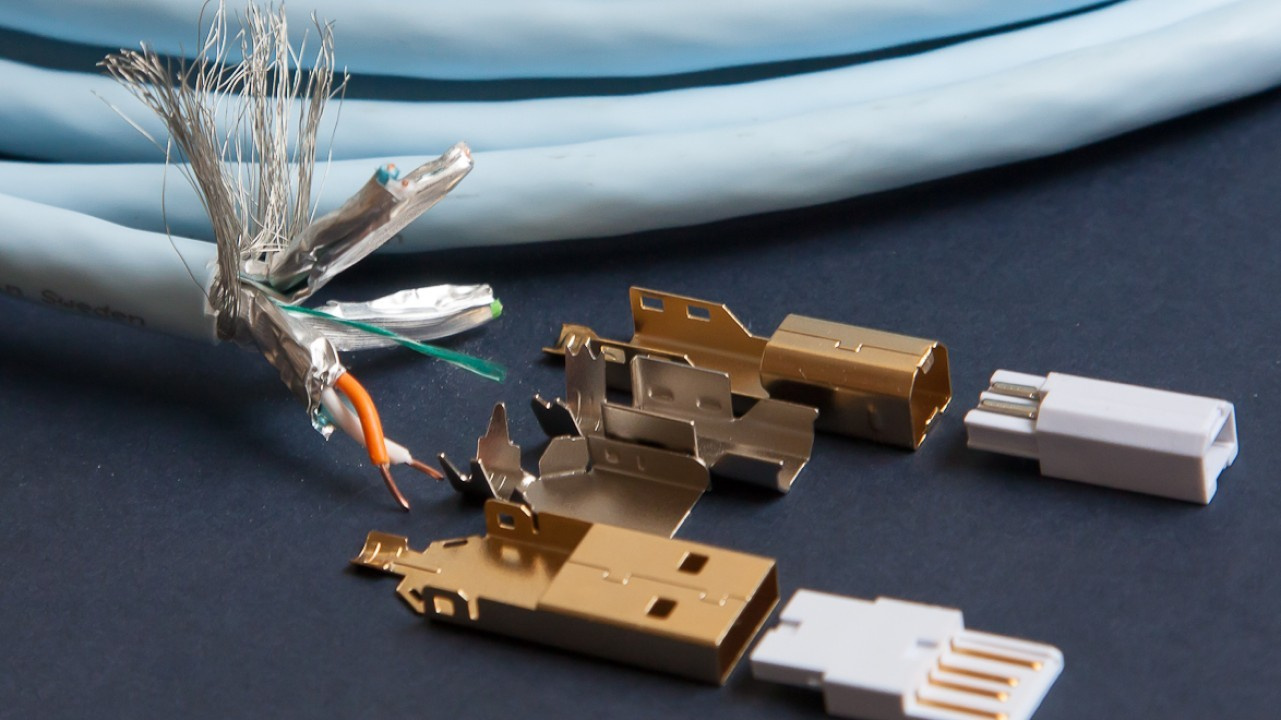
How Is a USB Cable Constructed?
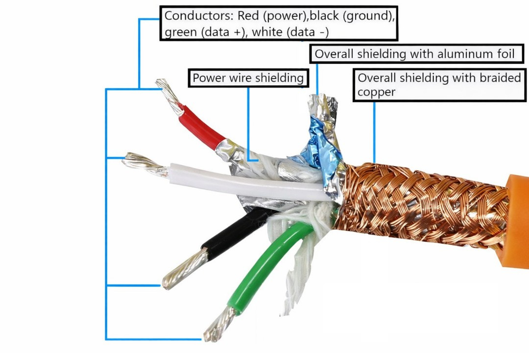
A USB cable uses four conductors, as follows:
• Power conductor: known as “VBUS,” insulated in red, providing a positive supply of 5 volts (+5 V).
• Ground conductor: known as “GND,” insulated in black, providing a neutral reference (0 V).
• Positive data conductor: known as “D+,” insulated in green, carrying a differential signal [1].
• Negative data conductor: known as “D−,” insulated in white, also carrying a differential signal.
[1] A differential signal is one in which the signal is transmitted through two conductors with opposite and complementary voltages.
High-Quality USB Cables: What Should They Do in Digital Audio Systems?
High-quality USB cables for digital audio systems should:
• Prevent data transmission errors.
• Provide protection against EMI and RFI noise.
• Prevent interference between data and power conductors.
• Provide a firm mechanical connection.
• Offer better signal stability compared with conventional USB cables.
What Characteristics Should a Good USB Cable for Audio Have?
For a USB cable to be suitable for audio, you should look for models with the following characteristics:
• Shielding
• OFC or OCC copper conductors
• USB connectors/plugs with metal housings
• Firm, play-free connections
• Twisted and balanced data conductors
• Physical separation between data and power conductors
How Is USB Cable Shielding Implemented?
USB cable shielding can be implemented in the following ways:
• Overall shielding: all four conductors of the USB cable are wrapped with an aluminum foil and braided copper shielding.
• Foil-shielded twisted pair (FTP): shielding of the data conductor pair, individually wrapped with an aluminum foil.
It is possible to have both overall shielding and shielding of the twisted data pair; however, the most common configuration is overall shielding only, often referred to as “double-shielded.”
What Is the Purpose of Shielding?
Shielding in USB cables is intended to prevent the following:
• Interference due to capacitive coupling
• EMI and RFI interference
• Digital clock noise
Capacitive coupling occurs when conductors are in close physical proximity, allowing high-frequency noise to couple from one conductor to another. This effect can be mitigated through the use of dielectric materials such as Teflon or by inserting a plastic separator in an “X” shape.
Electromagnetic interference (EMI) and radio-frequency interference (RFI) can introduce noise into audio signals, as explained in the article “How to Eliminate Audio Noise, Hissing, and Interference in Headphones and Speakers”.
Digital clock noise occurs when there is a timing error in the reading of digital audio samples, a phenomenon known as “jitter.”
What Is the Clock in Digital Audio? When Does Jitter Occur?
The clock is used in the process of converting a digital signal into an analog signal within a DAC. Its function is to determine the precise moments at which the digital audio data are processed, transmitted, and converted into an analog signal. Each processing moment is considered a “pulse.” When this pulse timing varies, “jitter” is generated, which is the fluctuation in the timing of data processing.
Why Is It Important for a Cable to Use OFC or OCC Copper Conductors?
The higher the purity of the copper, the lower the likelihood of instability in the transmission of data and power signals through the USB cable conductors.
What Are OFC and OCC?
OFC stands for “oxygen-free copper.” It refers to copper conductors with an oxygen content of 0.001% or less, which improves the electrical conductivity of the cable.
OCC stands for “Ohno Continuous Casting,” a casting method that enables the production of metals with very high purity. This results in even lower electrical resistance in power conduction compared with OFC cables.
Why Use USB Connectors/Plugs with Metal Housings?
By using metal connectors or plugs in USB cables, shielding against EMI and RFI interference is improved. In general, metal plugs are better constructed and provide a firmer, play-free fit in USB ports.
What Is the Importance of Having USB Cables with a Firm Connection?
USB cables with a firm connection prevent data loss and fluctuations in power transmission, in addition to avoiding the generation of noise in the audio signal.
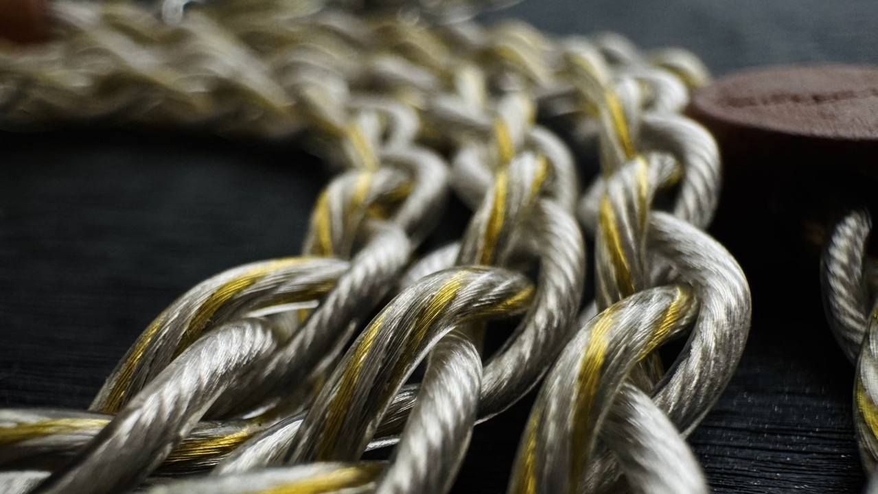
What Are the Advantages of Using Twisted and Balanced Conductors?
By twisting conductors of equal length and impedance (balanced conductors), EMI, RFI, and common-mode interference are minimized, as is capacitive coupling.
Why Physically Separate Data and Power Conductors in USB Cables?
By physically separating the data conductors from the power conductors in USB cables, the transfer of noise present in the power and ground conductors to the data transmission pair is reduced.
How Can Data and Power Conductors Be Separated?
There are three ways to separate data and power conductors:
• Using an internal plastic separator in an “X” shape to separate the data conductor pair from the power and ground conductors.
• Inserting dielectric materials (e.g., Teflon) internally to separate power conductors from data conductors.
• Dividing the USB cable so that it has two connectors/plugs: one dedicated to power and the other to data transmission, where the former is connected to a battery (power bank) and the latter to the DAC.
Do High-Quality Cables Make a Difference in Audio?
Yes. Well-constructed USB cables make a difference in audio performance because they prevent various types of interference and inconsistencies in the transmission of power and data signals. When a USB cable is poorly made, this is reflected in the audio in the form of noise, clicks, and distortion.
Share:

No comments have been made yet, be the first!