How to Eliminate Audio Noise, Hissing, and Interference in Headphones and Speakers
From: Vitor Valeri
A headphone hobbyist for over 15 years, he founded the Hi-Fi Hub website and is an administrator of the "Fones High-End" and "Fones Low-End" groups on Facebook.
Published in: 04/02/26 at 11:58
 Illustrative image of electrical grid interference generating noise in headphone and speaker audio
(Image: Pawel Czerwinski/Unsplash)
Illustrative image of electrical grid interference generating noise in headphone and speaker audio
(Image: Pawel Czerwinski/Unsplash)
Eliminating noise, hissing, and potential interference in the audio of headphones and loudspeakers can be a complex task. However, by identifying the possible causes and understanding how to prevent them, this process becomes more manageable. At the same time, it is important to keep in mind that each case is unique, and solutions are not always universal; therefore, a careful and methodical analysis of each situation is required.
It is possible to spend a significant amount of money when seeking “clean” and “stable” power to supply the equipment in a headphone or loudspeaker audio system. Nevertheless, there are several solutions that are easier and more affordable to implement. Even with relatively low investment, improvements in sound quality can be clearly perceptible.
Investment in Power Quality for Audio Equipment
By investing in solutions that improve the quality of the electrical power used to supply audio equipment, problems such as hum, hissing, and popping noises can be avoided. In addition, improvements in sound quality may occur, as unwanted noise will no longer interfere with audio reproduction.
An example of this is the investment I made in a dedicated grounding system for my headphone setup, combined with the use of an exclusive electrical subpanel for this purpose, separated from the main household electrical panel. The result was a lower noise floor, which made it easier to perceive musical nuances, improved clarity and separation, and gave the impression of a wider soundstage.
What Causes Noise, Hissing, and Interference in Audio?
Interference perceived as hum, hissing, and popping in headphone and loudspeaker audio systems may arise from electromagnetic interference (EMI), radio-frequency interference (RFI), ground loops, switching noise, voltage spikes or surges, and voltage sags (undervoltage events).
What Are EMI and RFI Noise?
EMI noise stands for Electromagnetic Interference. It is related to magnetic and electric fields that induce noise in cables and electronic circuits.
RFI noise stands for Radio-Frequency Interference. It consists of high-frequency radio signals that propagate through the air and along cables.
Sources of RFI Noise
RFI noise is generated by:
• Devices with switching power supplies: These generate waveforms rich in high-frequency harmonics that radiate through the air and along conductors (e.g., televisions, computers, chargers).
• Routers, mobile phones, and Bluetooth devices: These emit high-frequency radio waves whose harmonics can couple into poorly shielded audio cables or sensitive circuits.
• Televisions: Due to the use of processors, DACs, switching power supplies, and RF emissions (e.g., HDMI remote control signals), radiated interference is produced, particularly at frequencies above 100 Hz.
• Radio devices, transmitters, and modems: Because they operate by transmitting and receiving radio-frequency signals, electromagnetic leakage and noise may occur.
Practical Examples of RFI Noise in Audio Systems:
• Noise from a computer’s switching power supply reaching a DAC via USB.
• Wi-Fi or mobile phone signals being picked up by unshielded RCA cables.
Sources of EMI Noise
EMI noise is generated by:
• Switching power supplies
• Wi-Fi routers
• Computers
• Televisions
• Chargers
• Light dimmers
• Microwave ovens
• Electric motors (e.g., refrigerators, air conditioners, fans)
Effects of EMI and RFI on Audio
EMI and RFI can cause the following effects in audio systems:
• Intermittent hissing
• Low-level hum even with volume set to zero
• Pops or clicks originating from USB DACs
How to Mitigate EMI and RFI
To mitigate the effects of EMI and RFI, the following measures may be adopted:
• Use of shielded cables (power cables, RCA, XLR)
• Use of power conditioners
• Increasing the distance between Wi-Fi/Bluetooth sources and audio equipment
• Use of audio equipment with linear power supplies
What Are Voltage Spikes (Surges)?
Voltage spikes occur due to sudden and rapid increases in mains voltage, typically lasting only a few milliseconds. Voltage represents the “force” that drives electrical current through conductors and is commonly rated at 127 V or 220 V. Although voltage naturally fluctuates over time, it ideally should not vary by more than 5% from its nominal value.
The most common causes of voltage spikes include:
• Lightning strikes
• High-power devices using switching power supplies (e.g., air conditioners, refrigerators, lawn mowers, vacuum cleaners)
• Failures in the utility power distribution infrastructure
• Faulty equipment using switching power supplies or inverters
Effects of Voltage Spikes on Audio Equipment
Voltage spikes may cause the following damage to audio equipment:
• Failure of components (capacitors, transistors, among others)
• Reduced lifespan of MOSFETs and diodes in switching power supplies, leading to instability
• Audible pops during playback
• Digital data transmission errors in DACs
• Blown fuses
What Are Voltage Sags (Undervoltage)?
Voltage sags occur when there is a temporary reduction in the voltage supplied by the electrical grid. This typically happens during overload conditions, when overall energy consumption is high, but may also be caused by:
• Simultaneous operation of high-power appliances (e.g., refrigerator, microwave oven, electric shower, iron)
• Undersized household wiring (conductors with insufficient cross-section)
• Defective or distant street transformers
Effects of Voltage Sags on Audio Equipment
Voltage sags may cause the following issues:
• Reduced performance and noise in linear power supplies
• Distortion in amplifiers
• DACs restarting or becoming unresponsive
What Is Voltage Fluctuation in the Power Grid?
Voltage fluctuations are variations outside the nominal 127 V or 220 V levels. While minor fluctuations (around 5%) are considered normal, excessive variations may cause damage to electrical equipment.
How to Address Voltage Spikes and Undervoltage
To mitigate or eliminate voltage spikes and undervoltage issues, it is necessary to use equipment that filters and conditions the power supplied by the utility, such as power conditioners and power regenerators.
What Are Switching Power Supplies?
Switching power supplies regulate voltage and current with high energy efficiency, allowing for reduced size and weight. This regulation is achieved by rapidly switching the power on and off (typically between 20 kHz and 500 kHz). Each on/off cycle generates an electrical pulse, and the circuit controls the pulse width to regulate the energy delivered to the equipment’s components.
What Is Switching Noise?
Switching noise occurs during the operation of switching power supplies. As they repeatedly turn the power on and off, they inject electrical noise into the power line.
How to Reduce Switching Noise
Switching noise can be reduced by:
• Using power conditioners
• Employing audio isolators (magnetic and/or galvanically isolated USB devices)
• Using shielded cables kept as short as possible
• Maximizing physical separation between power cables and audio signal cables (RCA, XLR)
• Using equipment with linear power supplies
• Ensuring proper grounding and grounded outlets
What Are Linear Power Supplies?
Linear power supplies convert mains voltage using transformers and analog regulators, providing more stable power without generating high-frequency noise. Using DACs, preamplifiers, and headphone amplifiers with linear power supplies generally results in less electrical interference.
What Is a Ground Loop?
A ground loop occurs when two or more grounding paths with different electrical potentials are connected through the same electrical wiring.
Causes of Ground Loops
Ground loops are typically caused by:
• Duplicate grounding paths (e.g., a three-prong device connected alongside a two-prong device)
• Use of different outlets with different grounding references
• Data cables (HDMI, USB) sharing the same signal ground
• Equipment with antennas (e.g., televisions and computers with switching power supplies)
How to Prevent Ground Loops
Ground loops can be prevented by:
• Connecting equipment to outlets that share a single grounding point
• Separating data and power transmission using split USB cables (e.g., iBasso CB19)
• Transmitting data to DACs via optical connections instead of USB or coaxial
• Powering all equipment from a single outlet
USB Audio Isolators for Noise and Ground Loop Prevention
Audio isolators are used to prevent noise generated by devices with switching power supplies (e.g., computers), ground loops, and audible hum or hissing. By galvanically isolating the USB port, all four pins of the USB bus are isolated, eliminating direct electrical connection between the computer and the DAC and separating power delivery from data transmission.
Examples of USB audio isolators include the Topping HS02 and iFi iDefender.
What Are Harmonics?
Harmonics can be understood as “echoes” of a fundamental waveform, appearing at integer multiples of its frequency. For example, if the fundamental frequency is 60 Hz, the first harmonic is 60 Hz, the second harmonic is 120 Hz, the third harmonic is 180 Hz, and so on. Higher-order harmonics have lower amplitudes relative to the fundamental and contribute to harmonic distortion.
Harmonics in the Electrical Grid
In power grids, odd harmonics (3rd, 5th, 7th, etc.) are the most common and are also the most difficult to remove through power conditioning.
Switching Power Supplies and Harmonics
Due to switching noise in switching power supplies (commonly found in computers, routers, and electronic devices) very high-order harmonics are generated, as these supplies operate at frequencies above 13 kHz. These harmonics may propagate through the power grid or grounding system, interfering with audio equipment and producing noise or hissing.
How to Address Harmonic Issues in the Power Grid
The use of power conditioners combined with a properly implemented grounding system helps mitigate noise reaching audio equipment.
Simple and Cost-Effective Solutions to Prevent Noise and Interference
The simplest and most cost-effective measures to reduce noise and interference in audio systems include:
• Using a single grounding point or a dedicated ground for audio equipment
• Using USB cables with separate power and data lines or USB audio isolators
• Choosing equipment with grounded power connectors
• Keeping audio equipment away from Wi-Fi routers and Bluetooth devices
• Using hospital-grade outlets
• Preferring DACs with linear power supplies
• Maximizing distance between power cables and audio signal cables (RCA, XLR)
• Powering all equipment from a single outlet or from outlets sharing the same ground
• Using shielded cables, including power, RCA, and XLR cables
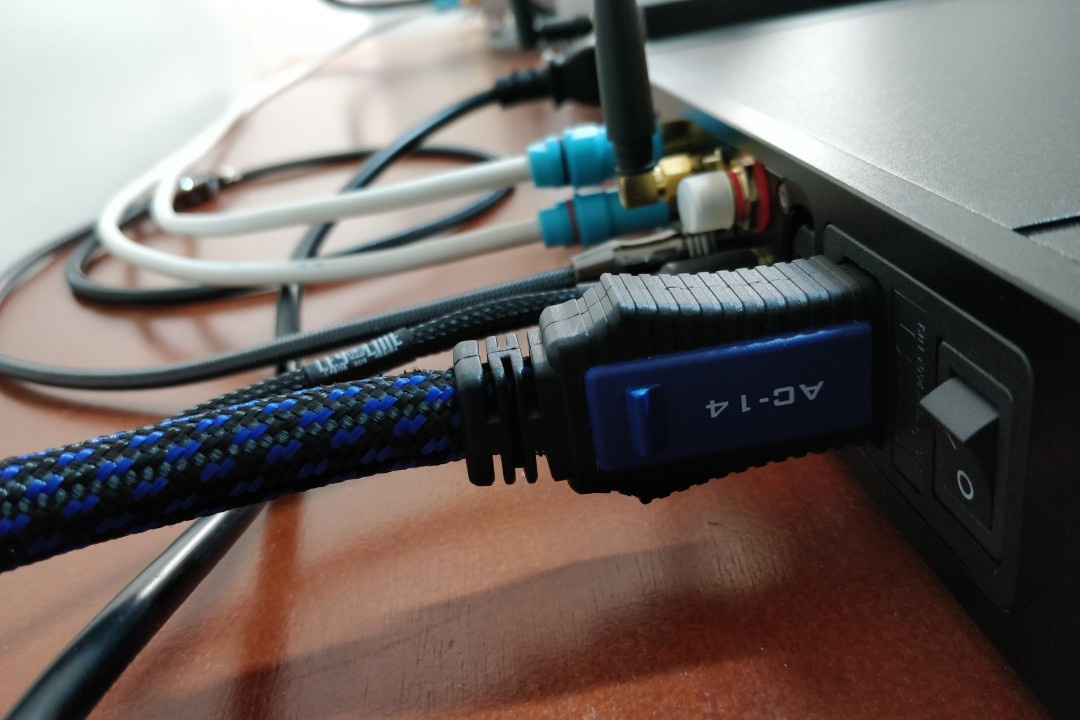
(Image: Vitor Valeri/Hi-Fi Hub)
Power Filtering and Conditioning Solutions
Power filtering and conditioning are essential to ensure interference-free power with reduced voltage, current, and frequency fluctuations. The following devices help minimize power-related issues:
• Power conditioners with active multi-band filtering: Filter EMI and RFI across multiple frequency ranges without affecting supply impedance.
• Power conditioners with toroidal isolation transformers: Isolate the audio circuit from the mains, eliminating common-mode noise [1].
• Power regenerators: Recreate a low-distortion sine wave (THD < 0.1%) using microcontrollers and internal DSP.
[1] Common-mode noise refers to electromagnetic interference that travels in the same direction along multiple conductors, such as phase and neutral.
The most comprehensive solution for power filtering and conditioning is the use of a power regenerator, which converts AC power to DC and then regenerates a new, clean sine-wave AC output with voltage and frequency fully controlled by DSP. Due to its high cost, careful evaluation is required to determine suitability for a given scenario.
Examples include the PS Audio DirectStream PowerPlant 12 and PowerPlant 15.
For users seeking better cost-effectiveness, active multi-band power conditioners offer a compelling alternative, as they remove noise across multiple frequency bands while maintaining stable impedance and phase coherence.
Examples include Panamax M5400-PM, Panamax M5300-PM, Furman ELITE-15 PF I, Furman PST-8D, Furman P-1800 PF, and Furman ELITE-15I.
A more affordable option that still provides meaningful benefits is the use of toroidal isolation transformer filters, which isolate the audio circuit from the mains and reduce noise.
Examples include Furman IT-Reference 7i, Torus RM 15, Isotek Titan, Upsine Power Line III Iso 2000, Ragtech IsoClean Pro, Embrastec IsoPower 2000, and Equi=Tech 2RQ.
Dedicated Electrical Installation for Audio Systems
Implementing a dedicated electrical installation facilitates the delivery of high-quality power to headphone and loudspeaker audio systems. A dedicated circuit minimizes voltage fluctuations and prevents interference affecting DACs, amplifiers, and music playback devices such as digital audio players and streamers.
Dedicated Electrical Subpanel
Sharing electrical loads with household appliances such as lighting, air conditioners, refrigerators, and washing machines can cause voltage fluctuations that interfere with audio equipment. For this reason, it is advisable to install a dedicated electrical subpanel exclusively for the audio system.
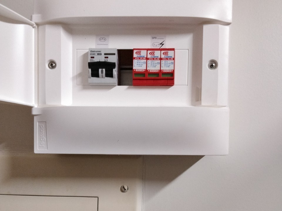
(Image: Vitor Valeri/Hi-Fi Hub)
This subpanel should include circuit breakers, surge protection devices (SPD), and residual current devices (RCD) and be connected to the main panel via an equipotential bonding conductor. A dedicated grounding system for the audio subpanel is also essential.
Wiring Recommendations
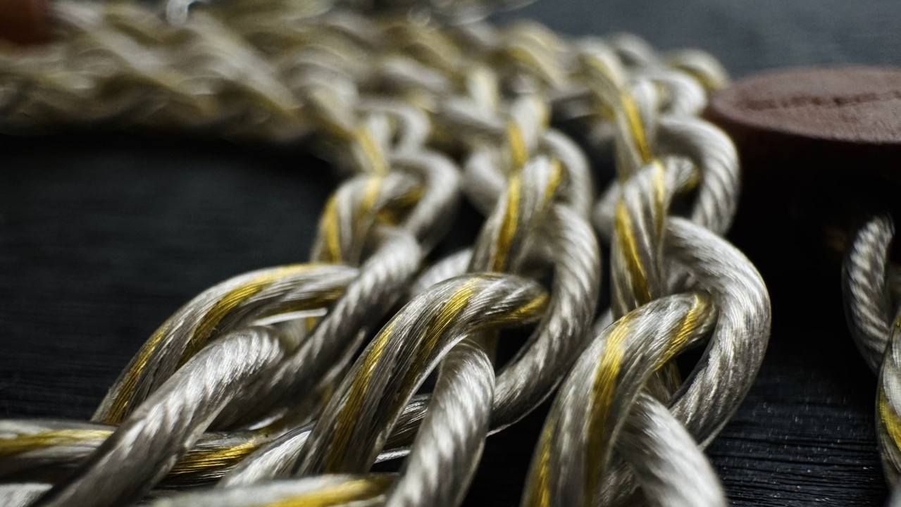
For optimal audio performance, the following wiring configuration is recommended:
• From the main panel to the audio subpanel: Solid conductor (Class 1), 100% OFC copper, 4 mm² cross-section, suitable for fixed installations.
• From the audio subpanel to wall outlets: Semi-rigid or flexible conductors (Class 2 or Class 5), 2.5 mm² cross-section, providing improved contact and reduced noise.
Conductor Flexibility Considerations
Solid conductors (Class 1) provide lower electrical resistance and are suitable for fixed installations. Flexible conductors (Class 5) are more resistant to vibration, maintain firm contact at terminals, and are less susceptible to microphonic effects.
Brazilian standards (NBR 5410:2004) permit the use of solid conductors in residential installations, provided they are installed correctly. The standard prohibits improper conductor selection, excessive bending, poorly tightened connections, and mixing rigid and flexible conductors without appropriate terminals.
Grounding Requirements
Dedicated grounding for audio systems should present resistance between 2 and 5 ohms. While NBR 5410 allows residential grounding up to 10 ohms, IEEE Std 142 (Green Book) and IEC 60364-5-54 recommend values below 5 ohms for sensitive installations and between 1–2 ohms for critical electronic systems.
Achieving grounding resistance between 2 and 5 ohms provides:
• Efficient leakage current dissipation
• Greater ground potential stability
• Reduced ground loop risk
• Lower EMI and ground noise
• Improved system noise floor
Grounding Optimization Techniques
Grounding resistance can be improved by:
• Using a dedicated equipotential busbar connected to the main ground
• Employing short, thick equipotential bonding conductors (minimum 16 mm²)
• Treating soil with charcoal, salt, and bentonite to enhance conductivity
• Using 6 mm² bare copper conductors or insulated green-yellow conductors per NBR 5410
• Installing multiple interconnected ground rods in a triangular configuration
Post-Installation Recommendations
After completing the dedicated electrical installation, it is recommended to:
• Measure outlet voltage using a True RMS multimeter
• Verify correct outlet polarity
• Periodically inspect grounding in humid environments
• Retighten terminals and breakers annually to prevent arcing
Is Investing in Power Quality Worthwhile?
After investing in dedicated grounding and an exclusive electrical subpanel for my headphone system, I observed a lower noise floor, improved perception of musical nuances, enhanced clarity and separation, and the impression of a wider soundstage.
Share:


No comments have been made yet, be the first!